Tour Map
The Tour Map is used to not only add location information to nodes and to view node location, but it is also a place to link nodes together to create a tour using maps and floor plans.
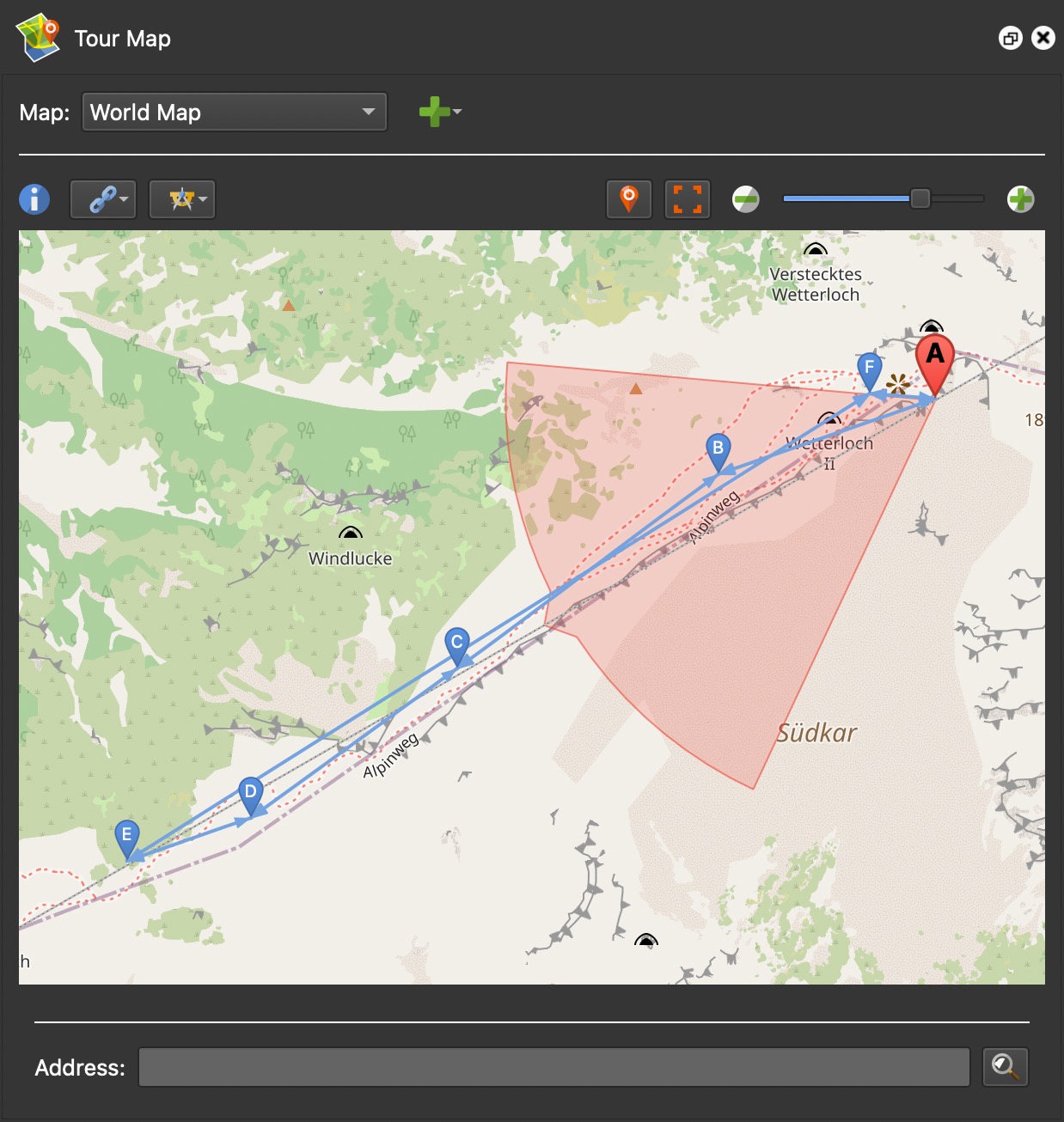
Map
Choose a map to add. World Map is the default map that is based on OpenStreetMap tiles. World Map Topo and Google maps are also available. The default map can be changed in Pano2VR’s Settings > Images > Default Map.
Click the Add Map button (green plus) to add a map or floor plan. Once a map has been added, the the Remove Map button will appear. Use this to delete the selected map.
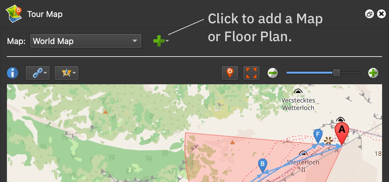
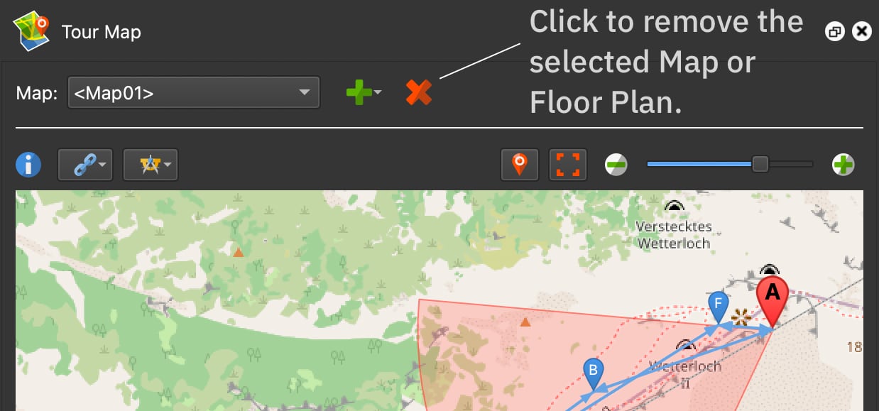
Add Map
This option will create a new map. The Properties panel will open and display the settings for the map. Each map is given a unique ID (Map ID) that can be called for in a Map element.
Give the Map a Title for easier identification. In the list of maps, the Title will be used instead of the Map ID. Also, if using a floor plans cloner, the title will be used here.
Choose a map provider. The settings will change depending on the provider chosen. Learn more about adding Maps.
Add Floor Plan
When adding a Floor Plan, you’ll be prompted to choose an image file (your
floor plan). This, too, will be given a unique ID, like FloorPlan01 and can be
chosen as the map to use in the
Map element.
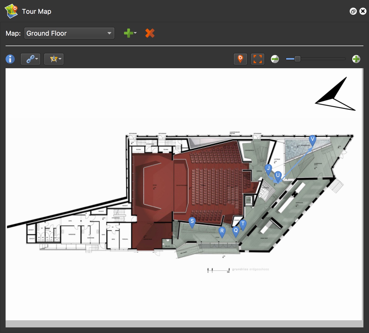
When the Floor Plan is added, the Properties panel will open and display the settings for the map.
Linking Options
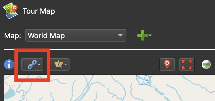
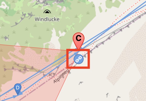
Linking can be done either automatically or manually. To link manually, activate Link Mode by hovering over a node marker in the map and click the link icon.
Click the Linking Options button in the Tour Map for the following options:
Link Both Ways – Select to link nodes in both directions. A node linked both ways is indicated by arrows on both ends of the blue linking line and has a darker shade of blue. When not selected, only one direction is linked in Link Mode.
✭ To remove a link, select the blue line and hit delete. When in Link Mode, hold Alt or Option and click the connecting node to remove the link(s). Both directions are removed if Link Both Ways is selected. Only one direction is removed if Link Both Ways is not selected.
Switch Node in Link Mode – Select this to switch to the linked node when creating a link in Link Mode. When not selected, the originating node stays active. Links can also be deleted while in this mode by pressing Alt [win] or Option [macOS] and clicking the blue link.
Show All Links – Select this option to show all the links between nodes. Links are the blue lines between map markers. If not selected, only links to and from the currently active node are shown.
Automatic Linking
The following options let you choose the automatic linking mode.
★ Images must be geotagged and their north directions correctly set for automatic linking to work. Learn how to add location data.
Sequential – The nodes will be linked together in their order in the Tour Browser.
Closest Node – The nodes will be linked to their closest neighbor based on GPS data, or when using a floor plan, their position on the floor plan. ✭ This is the suggested mode for uploading to Google Street View.
From Current Node – If a single node is selected/active, then links will be created to all other nodes in the project. If multiple nodes are selected, links will be created from the active node to all other selected nodes.
Complete – This links each node to every other node in the tour. ✭ Caution: This may result in many hotspots in each node.
Remove All Links – Click to remove all links.
✭ To remove individual links, select the linking line and hit the delete key.
Tools
This button shows all modes available that help in setting a node’s location and orientation. You can also add a grid and change the color of the map’s radar.
Measure Distance – Use the Measure Distance mode to measure a floor plan’s size. This is needed if you’d like to integrate the map with the world map. This is useful for indoor tours.
Pick Landmark – Pick Landmark mode is used for finding a node’s North position. See: Set North with Pick Landmark
Geolocate Map – This mode allows for floor plan placement on the world map and then GPS data can be applied to the nodes. This is particularly useful for tours that are taken indoors where location data is not available.
Pick Place ID – When Google Maps is open, this option will be available. Here, you can choose a specific place (POI) for Google Street View.
Set Map Limits – Limit how far one can move within a map. This helps prevent users from losing their spot in the map. To create a limit, first add a map. Click Set Map Limits and then drag the mouse to cover the area that will be visible. Once the limits have been drawn, you can drag the edges to refine the area.
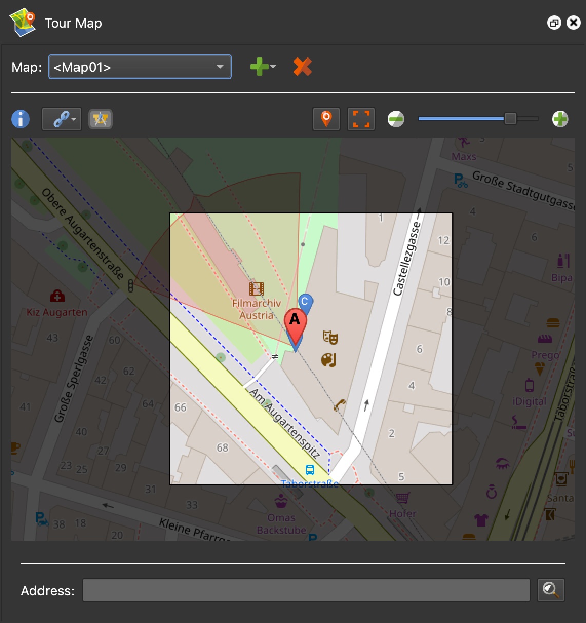
The limits’ coordinates will be shown in the Map properties. You can also activate Limits Mode here and reset them.
Toggle Grid – A grid can be added to help facilitate map pin placement as the pins will snap to the grid. This is especially useful for Street View tours. To turn the grid off, click Toggle Grid again. The grid is visible when zoomed to about level 19, depending on the grid spacing.
- Grid Spacing – Change the grid size. Units can be measured in Meters, Feet, and Miles.
- Angle – Adjust the angle of the grid lines.
- Color – Choose the color of the grid lines.
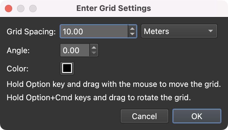
Move the grid with keyboard shortcuts:
- Alt-drag/Option-drag to move the grid
- Ctrl-Alt-drag/Option-Command-drag to rotate the grid. The center of rotation will be the mouse cursor.
The grid is stored in the project file.
Set Radar Color – Change the color of the radar beam. This is useful if the default color of the beam is hard to see. This change is not seen on output. To change the radar beam’s color in the skin, adjust the color setting in the Map Element Settings.
Position Map
Center Current Node – Centers the currently selected node on the map or floor plan. Alt-click or Option-click the button to lock it so when switching to a different node it will also appear centered in the Tour Map.
Fit Nodes in Window / Fit Floor Plan in Window – Fits all nodes within the window, or in floor plan mode, fits the floor plan image within the window.
Zoom – Use this slider to zoom in and out of the map or floor plan. Hovering over the slider will reveal the current zoom level. This is useful for setting zoom levels in a custom map.
Move Map Pins
To move a single pin, drag it to its new location.
To move pins that are not currently selected, press Alt and then drag the inactive pins.
To move a selection of pins:
-
Press Shift and drag over the pins to select them.
-
Press Command (macOS) or Control (win) to view the selected area then drag the selection to move the pins at the same time.
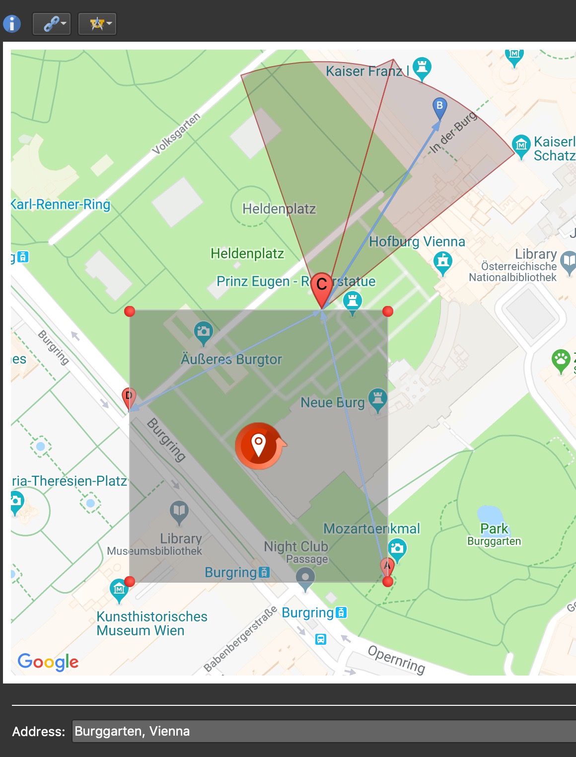
-
While pressing Command/Control, drag the corner handles to reposition the pins. The pins move relative to the box; their distances change based on the box’s aspect ratio.
-
Press Command-Shift or Control-Shift and drag on the box’s handles to keep the box’s aspect ratio fixed.
-
Press Command and click in the outer area of the center control to rotate the selection.
List of Keyboard Shortcuts available for tasks in the Tour Map